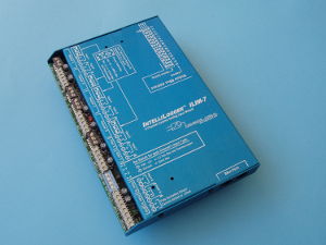
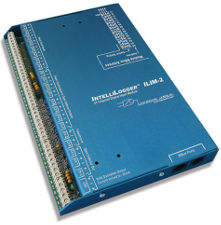
IntelliLogger™ IL-90
3 Analog plus 22 Digital Inputs / 10 Outputs, Network enabled Data Acquisition instrument with I/O Expansion capability
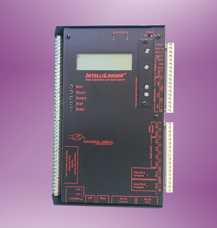
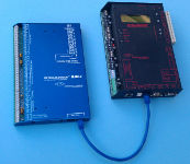
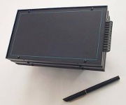
The IntelliLogger IL-90 is a single package solution for data acquisition and reporting applications requiring a high quantity of digital inputs and outputs. The IL-90 is effectively a basic IntelliLogger IL-20 and ILIM-2 Digital Expansion Module packaged into a single enclosure. The result is a powerful IntelliLogger with a tremendous quantity of digital I/O coupled with some basic analog channels. The digital I/O can be user configured in a mix of Event, Counter or Frequency input and Open Collector (switched) outputs.
The IL-90 includes capability to add on additional analog and digital I/O Expansion Modules via the integrated daisy-chain BBus port. The IL-90 is provided with a suite of hardware I/O to meet many basic data logging applications and offers the same full network communication, reporting and alarming capabilities of the other IntelliLogger models. The IL-90 also supports the optional Modbus RTU feature which allows for data collection from Modbus connected Slave devices.
As with other IntelliLogger models, the IL-90 is graphically programmed with the included powerful and intuitive HyperWare-II software. The IL-90 is equally suited for stand-alone, low-power operation as well as network connected (Ethernet, WiFi or cell modem) data acquisition, alarming and reporting applications.
A full suite of balance of system accessories are available ranging from weather/tamper-proof enclosures with optional battery packs, sensor excitation power supplies and more.
| IL-90 Key Features | |
|---|---|
| 22 Digital Inputs, 10 Outputs and 3 Analog inputs | |
| Rugged design for all environments… remote site, plant floor or lab | |
| Stand-alone or Network / Cellular connected for remote access, Reporting and Alarming | |
| Easily programmed… provided with intuitive HyperWare-II icon-based programming software | |
| Integral Web Page server allows browser access to real-time values and data transfers | |
| Modular Design for field I/O expansion | |
| Modbus RTU Master, Slave and Modbus TCP options | |
| Easily Programmed for Intelligent and Conditional Logging Strategies | |
| Low Power consumption allows for battery, photovoltaic, and/or line powered operation | |
| Uses include field test, Sub-Metering, inventory monitoring, Process alarming, Energy logging, Demand studies, troubleshooting and more |
Product Information
Overview
The IntelliLogger™ Network Enabled Data Logging and Alarming System is a versatile stand-alone data acquisition, alarming and reporting instrument that incorporates a full suite of Network capabilities. With this added Network connectivity, not only can the IntelliLogger sample analog and digital inputs, process them and log them to memory… but it also can report and alarm in a powerful new variety of methods. Additionally, the IntelliLogger monitoring your connected equipment can now be accessed over the Internet to view current values, download logged data, acknowledge alarms and more.
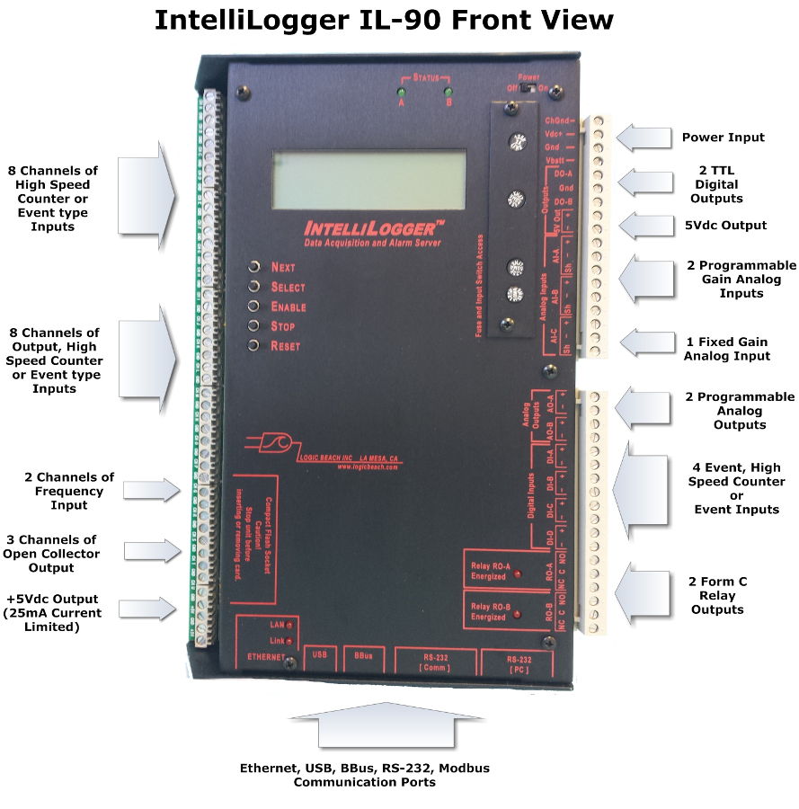
The IntelliLogger IL-90 model consists of the standard IntelliLogger base (IL-20 model) bundled with an ILIM-2 Digital I/O Expansion Module in a single rugged package. To the analog and digital I/O on the base IL-20, the integrated ILIM-2 Module adds multiple user configurable digital channels including:
- 8 channels of Event/Counter Input
- 8 channels of Event/Counter Input or Open Collector Output
- 2 Frequency Inputs
- 3 Open Collector Outputs
- 1 0/+5Vdc Output
Additional analog and digital channels can be added to the IL-90 by connecting one or more analog (ILIM-7) or digital (ILIM-2) expansion modules via the standard BBus interface.
All IntelliLogger models have Modbus RTU Master, Modbus RTU Slave and Modbus TCP Server as options. With the Modbus RTU Master option, the IntelliLogger can acquire register values from multiple Modbus RTU Slave devices. The Modbus register value is then processed within the IntelliLogger as other hardware analog or digital inputs.
Configured with the Modbus Slave or TCP Server options, the IntelliLogger can provide register values to other Modbus Master or Client devices.
All models of the IntelliLogger utilize the powerful and intuitive HyperWare-II software for programming. HyperWare-II facilitates a quick learning curve due to its graphic programming User Interface. Simply dragging icons onto the workspace then interconnecting the icons with your mouse defines program function. This program is then uploaded to the Intellilogger memory where it executes stand-alone.
Options for the IL-90 include Modbus data collection, cell modems, WiFi interconnect, weatherproof enclosures, battery packs and more.
Specifications
The IL-90 provides a full selection of digital I/O complementing the analog and digital I/O on the IntelliLogger system base. Channel capacity added in the IL-90 is shown below as well as displayed pictorially in the IL-90 Front View image. Refer to the IL-20 Specifications for channels provided by the IntelliLogger base component of the IL-90.
IL-90 Inputs and Outputs (in addition to the Base IL-20 I/O specified below)
| Feature | Channel Qty | Function | Comments |
|---|---|---|---|
| Event or Count Input |
8 (Chans A through H) |
Event or High-Speed Count (e.g. for sub-metering apps) Signal Debounce is software configurable on a per channel basis. Fixed integral pull-ups allow for “dry” contact (non-powered switch) inputs. Can also accept Vdc driven input signals up to 5Vdc. Schmitt circuitry adds hysteresis for slower transitioning input waveforms. |
Channels are individually configurable through HyperWare-II as Event or High-Speed Counter inputs.
Event Mode: Input’s state is sampled at a frequency as defined in the IntelliLogger Program Net. Input only stored when it changes state (On to Off or Off to On). Counter Mode: Per sample rate in IntelliLogger Program Net, the count total is periodically sampled and stored to memory or used in further processing (e.g. totalization, KWh calculations, volume flow, etc) |
| Event, Count Input or Open Collector Output |
8 (Chans I through P) |
Event, Count input or Open Collector Output. Signal Debounce is software configurable on a per channel basis. Fixed integral pull-ups allow for “dry” contact (non-powered switch) inputs. Can also accept Vdc driven input signals up to 5Vdc. Schmitt circuitry adds hysteresis for slower transitioning input waveforms. Use: Sub-metering inputs and general use outputs |
Same as Inputs above with the addition of Open Collector outputs (100mA max) for each channel with over-current and ESD protection. |
| Frequency Input |
2 (Chans Q & R) |
Frequency input channel. Software controlled pull-ups allow for “dry” contact (non-powered switch) inputs. Can also accept Vdc or AC input waveforms up to +/-12V. | Connected input signal’s frequency is sampled periodically per the IntelliLogger Program Net and passed along for storage to memory or further processing and calculations.
Input is amplified. Expanded frequency range results when input waveform amplitude is larger. |
| Open Collector output |
3 (Chans S, T and U) |
Open Collector output |
Output: 100mA. Over-current protected. Frequency Output Mode:Under IntelliLogger Program Net control, these outputs can be configured to generate a varying square wave output as a function of the Program Net parameters. |
| +5Vdc Output | 1 | +5Vdc regulated output | Output is under IntelliLogger Program Net On/Off control. Current limited to approximately 25mA |
Hardware Features in the IL-20 Component of the IL-90
| Feature | Channel Qty | Function | Comments |
|---|---|---|---|
| Analog Input (programmable range) | 2 | Vdc Input ranges: -10 to 20mVdc -35 to +60mVdc -45 to +80mVdc -60 to +100mVdc -120 to +200mVdc -300 to +500mVdc -600mV to +1.0Vdc -1.2 to +2.0VdcThermocouple: J, K, E, T, R, S and N typesmAdc Input ranges: -100 to +200uAdc -350 to +600 uAdc -450 to +800uAdc -600uA to +1mAdc -1.2 to +2mAdc -3 to +5mAdc -6 to +10mAdc -12 to +20mAdc |
Channels can be field configured for Vdc input, Thermocouple input or mAdc input. These channels utilize a 12 bit ADC providing approximately 1 part in 4000 resolution over the full scale.
NOTE: For higher resolution needs, the IL-80 and/or the ILIM-7 analog input expansion module can provide up to 20 bits (!) of resolution which equates to 1PPM. When channels are configured for thermocouple applications, the CJC temperature is automatically sensed and used in compensation. |
| Analog Input | 1 | Vdc Range: 0 to 3.2Vdc mAdc range: 0 to 32mA |
Field configurable for a single range of mAdc or Vdc input. 12 bit resolution. |
| Internal Temperature Sensor | 1 | Used for CJC for System Base thermocouple measurements | Sensor can also be used for monitoring or logging of IntelliLogger temperature per user’s Program Net. |
| Digital Input | 4 | Frequency: 10Hz to 20Khz with 100mVpp sine input. 0.04Hz to 120KHz with 1Vpp input signal. Frequency measurement range expands further with increased input signal amplitude. Count: 0/ 3V input (0/24Vdc max) signal, 0 to 25KHz input pulse frequency without missed counts Event: 0/3Vdc minimum, 0/24Vdc max driven input |
Programmable as Event, High- speed counter or Frequency input per channel.
Channels are provided with debounce and pull-up under program control allowing for non-powered (contact closure, transistor or opto) inputs for Event, Frequency and Count functions. |
| Analog Output | 2 | 0 to 10Vdc (8 bit) | Under IntelliLogger program control. 10Vdc output requires unit supply voltage to be >10.5Vdc. |
| +5Vdc Fixed Output | 1 | 0/5Vdc output; current and short circuit protected at 25mA | Control via IntelliLogger program |
| Status LED | 2 | Green LED output | Control via IntelliLogger program |
| Relay Output | 2 | Form C (NO, NC and Com) | Control via IntelliLogger program |
| TTL Output | 2 | 0/5Vdc current limited outputs | Control via IntelliLogger program |
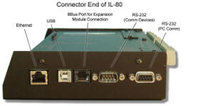
| Ethernet Port | 1 | 10base-T | Modbus TCP Server option is available for this port. Cellular network modem uses this port. |
| RS-232 (PC) | 1 | DB-9F for PC Communication | Modbus RTU Slave option is available for this port. |
| RS-232 Comm | 1 | DB-9M for external comm device support (modems, radios, etc) | |
| USB | 1 | For PC Communication | |
| LCD Display | 1 | 4 line x 20 Characters | Status messages as well as custom messages under program control |
Programming
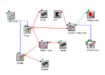
Programming consists of connecting Input, Output and Function icons together with a mouse to construct a “HyperNet” Program. Clicking on each of the icons displays a Configuration Dialog to enter desired settings. Once the HyperNet is built, it is then uploaded to the logger memory where it executes stand-alone… sampling inputs, performing math, logic, storage to memory, output alarming, reporting and more. Due to the graphic design method, HyperNet programs are intuitive to construct and easy to comprehend at a later date… an extremely valuable feature.
In addition to the programming capability included in HyperWare-II, remote control communications, data downloads and Real-Time trending features are provided. With the Real-Time Trending feature, custom dashboards can be built to display sampled inputs, calculated values and output states in a variety of graphical display objects such as thermometers, line plots, charts, gauges and much more.
I/O Expansion
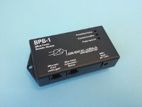
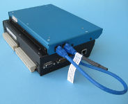
Additional analog (thermocouple, voltage, current) and digital (Event, Frequency, Counter and output) channels can readily be added to IntelliLogger models with the connection of ILIM-7 or ILIM-2 Expansion Modules. Intelliloggers equipped with the BBus expansion port capability (IL-20, IL-80, IL-90) are expanded by simply daisy-chain connecting one or more Expansion Modules. A CAT-5 Ethernet cable is used (provided with the module) for the interconnection and up to 100’ can separate the IntelliLogger and a module. For applications with 5 or less modules, the IntelliLogger System Base can provide both the communication AND the power for the modules via this BBus interconnect. For systems utilizing more than 5 Expansion Modules or long interconnecting runs, a BPB-1 BBus Power Booster can be used to inject power into the BBus daisy-chain network.
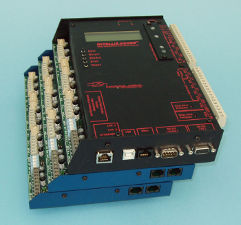
Expansion Modules stacked on IntelliLogger Base
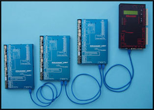
IL-20 with daisy-chained Expansion Modules
Options
With the suite of new Modbus Options, the IntelliLogger can now be utilized in Modbus network applications. A Modbus RTU Master enabled IntelliLogger can read Modbus register parameters from a connected Modbus Slave device (e.g. a flow computer, transducer, etc) along with other conventional hardwired inputs (e.g. thermocouples, pressure transducers, etc). These Modbus garnered values can then be processed, reported, stored to memory, embedded into emails, FTP’d and/or served up in Web pages… all by the IntelliLogger.
Alternatively, the IntelliLogger can be configured as a Modbus RTU Slave (or Modbus TCP Server) and share its own internal Modbus registers for interrogation or update from other networked Modbus Master (Client) devices.
Documentation
Frequently Asked Questions
- What is the difference between IntelliLogger models?
- The IL-10 is the most basic stand-alone model.
- The IL-20 is identical to the IL-10 with one exception… its Input/Output channel count can be expanded with the connection of additional Expansion Modules such as the ILIM-2 and the ILIM-7 via the BBus port.
- The IL-80 is simply an IL-20 with one ILIM-7 Analog Expansion module housed in a single instrument package. The IL-80 can be expanded with even more channels with the addition of ILIM-2 and ILIM-7 modules.
- The IL-90 is simply an IL-20 with one ILIM-2 Digital Expansion module housed in a single instrument package. The IL-90 can be expanded with even more channels with the addition of ILIM-2 and ILIM-7 modules.
- What components do I need to order to make a complete usable data acquisition instrument?
- Simply ordering the Part Number associated with the IntelliLogger on the Ordering Tab will provide a complete usable instrument.
- The unit is supplied with a wall adapter power supply, USB and Ethernet cable and a CD containing the HyperWare software and the complete user manuals in PDF format.
- If not ordered with the IntelliLogger, the customer will need to provide a PC computer with USB port and any sensors or signals to be sampled by the IntelliLogger.
- How can I get more Input/Output channels?
- The IL-20, IL-80 and IL-90 can have multi-channel Expansion Modules connected to increase the channel count. The modules are daisy-chain connected to the IntelliLogger with Ethernet cables via the integral BBus port.
- Will the IntelliLogger run stand-alone without a PC connected?
- Yes. Once the IntelliLogger is programmed, it can run stand-alone sampling inputs, performing calculations, driving outputs, etc. Options include various battery options to implement true stand-alone operation.
- Does the IntelliLogger provide power for sensors?
- It depends. There is one 5Vdc regulated output as well as two programmable analog voltage outputs on all IntelliLoggers. These can be used to provide excitation for many types of sensors. For transducers requiring higher voltages, we offer the PSM-2 Power Supply Module that can step up the nominal 9Vdc voltage provided by the optional D-cell Battery Pack or an external supply voltage to 10, 15 or 24Vdc. Those voltage levels will typically provide transducer power or loop excitation for 4-20mA transmitters.
- I am running the IntelliLogger from batteries.. how can I power transducers?
- Use the PSM-2 module (see above) to step up battery voltage to levels sufficient to power most transducers. Addtionally, to conserve battery energy in slower sampling applications, the power to the transducers can be cycled on before a reading then off after the reading.. saving battery energy. This is commonly done with the Warm-Up Icon.. a standard feature in the HyperWare software.
- Is the IntelliLogger weatherproof?
- No, however we offer tamper/weatherproof enclosure options. Refer to the Enclosure Options in the Accessories Tab for details
- What can be viewed on the IntelliLogger front display?
- Front panel buttons allow users to step through liquid crystal display (LCD) menus to view:
- System Status (Enabled/Stopped, Memory usage, Supply voltage, IP address, etc)
- Real-time values associated with any Probe Points included in the Program Net.
- User defined messages displayed per the Program logic
- System Error messages (Memory Full, Low Supply Voltage, etc)
- and more….
- Front panel buttons allow users to step through liquid crystal display (LCD) menus to view:
- Can a cellular modem be used with the IntelliLogger?
- Yes, we offer cell modems compatible with the major cellular carriers.
- Can the IntelliLogger be connected to a local area network (LAN)?
- Yes, there is an included Ethernet port integral to the IntelliLogger. Once the LAN parameters (IP address, Gateway addresses, mail servers, etc) are configured via USB, the IntelliLogger can be directly connected to the LAN with a Cat 5/6 cable and accessed from anywhere on the LAN.
- Can the IntelliLogger connect to a WiFi network?
- Yes, we offer a WiFi bridge that connects to the IntelliLogger Ethernet port and allows wireless communication to a conventional Access Point on a LAN.
- Can I access a LAN connected IntelliLogger remotely from outside of the network?
- Yes, providing that a Port can be opened up in the network firewall to allow outside access to the IntelliLogger. Once this Port is open, communication with the IntelliLogger is possible from networks anywhere in the world. Passwording can be set on the IntelliLogger to limit access.
- What capabilities do I have via a remote connection to the IntelliLogger?
- All of the commands that can be performed via a USB connection can be performed remotely via a LAN, WiFi or Cell Modem connection. Assuming you have password rights this includes:
- View real-time values
- Data download
- Reprogramming
- Enable / Stop / Erase Memory
- Status view
- Change Program execution via Remote Control Switch Icons or Remote Constant Icons (if they are included in the executing Program Net)
- All of the commands that can be performed via a USB connection can be performed remotely via a LAN, WiFi or Cell Modem connection. Assuming you have password rights this includes:
- Can I prevent unauthorized access to the IntelliLogger?
- Yes. The IntelliLogger has a powerful Password authentication system. Multiple User accounts can be built with varying Permissions. For example, an Operator User could be set up to allow for viewing of real-time values but can’t reprogram the unit. A Power User might be able to Perform all functions but NOT reprogram the unit, etc.
- What happens if a power failure occurs?
- The IntelliLogger will shut down upon a power failure and save all current readings to non-volatile memory. When the power returns, the IntelliLogger will reboot and resume the operational mode which it was in prior to the power failure.
- Can I use a backup battery to power the IntelliLogger through utility outages?
- Yes, the IntelliLogger can be connected to both a low voltage utility source (eg the provided 120Vac to 12Vdc power adapter) and to a nominal 9Vdc Battery Pack option. If the utility power fails, the IntelliLogger will automatically switch to the backup battery and continue operation. When the utility power resumes, the IntelliLogger will commence operation from the utility source again. If running from a nominal 12Vdc source battery as backup, use of a 120Vac to 24Vdc adapter will ensure the IntelliLogger only draws current from the battery when the utility fails.
Ordering
| IntelliLogger IL-90 | |||
|---|---|---|---|
| Product Name: | IntelliLogger IL-90 | ||
| Order Part Number: | 9080.50030 | ||
| Price: | $2060 | ||
| | | |||
| Items included with order: | |||
| Product Name: | Part Number: | Qty: | |
| IntelliLogger IL-90 | 9080.50030 | 1 | |
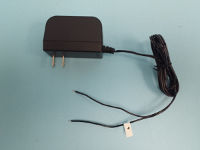
| Power Supply, wall outlet (DCXF-12V-1A) | 9080.00002 | 1 | |
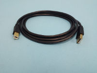
| Cable, USB, Type A to B, 6′ | 9020.40000 | 1 | |
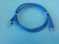
| Cable, Cat 5, Ethernet Standard, 10′ (CBL-E-S-10) | 9020.50012 | 1 | |
| HyperWare-II software with complete PDF User Manuals (instrument and HyperWare) | CD | 1 | |
| | | |||
| Items commonly purchased with this product: | |||
| Product Name: | Order Part Number: | Price: | |
| IntelliLogger Surface Mounting bracket | 3539.30010 | $22 | |
| Compact Flash memory card (CF-IND-128MB) | 9080.03100 | $72 | |
| ILIM-7 Analog Input channel Expansion Module | 9080.50002 | $840 | |
| ILIM-2 Digital Input channel Expansion Module | 9080.50001 | $780 | |
| Enc250 Weatherproof Enclosure | 8050.91250 | $280 | |
| Cellular Modem for remote site communication | 9080.5046x | $589 | |
| Power Supply, 24Vdc wall adapter (commonly used to provide IntelliLogger power and transducer power) | 9080.00017 | $30 | |
| SCC-1 Serial Comm Converter for Modbus RS-485 | 9080.50100 | $168 | |
Contact Logic Beach directly to purchase this product.
Contact Logic Beach directly via phone or email with questions and/or to place your order.
Our Applications Staff welcomes your inquiry!
Accessories
ILIM-7 IntelliLogger Analog Input Channel Expansion Module
Isolated 8 channel analog input expansion module for the IntelliLogger™ system.
ILIM-2 Digital Input/Output Channel Expansion Module
Event, Counter, Frequency Input and Digital Output channel expansion module for the IntelliLogger system.
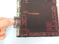
CF Memory Card
Insert to enlarge data storage capacity as well as facilitate logged data transport.
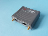
Cellular Data Modems
Connection of a cellular modem facilitates M2M remote access to the ILL via the cellular data network.
Enclosures
Weather and tamperproof protective enclosures.
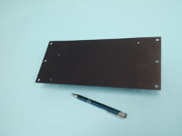
Surface Mounting Bracket
For attaching ILL or Expansion Modules to a wall or enclosure back.
PSM-2 Sensor Excitation Power Supply
Step up power supply to provide cycled sensor excitation or 4-20mA loop power from batteries or nominal 12Vdc source.
PSM-2-PP Sensor Excitation Power Supply
A stand-alone portable power supply including 6 D-Cell and the PSM in a small (4.8 x 8.8 x 2.9) package.
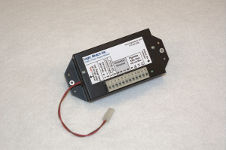
BPB-1 BBus Power Booster
Injects supply voltage in BBus network for applications with 5 or more Expansion Modules or long BBus cable runs.
SCC-1 Serial Comm Converter
Converts ILL RS-232 port to RS-485 for Modbus RTU applications.
Expansion Module Attachment Bracket
Allows stacking of Expansion Modules and/or attachment to the IntelliLogger base.
120/240Vac 12Vdc Power Supply
Provides 12Vdc power for IntelliLogger operation.
120/240Vac 24Vdc Power Supply
Provides 24Vdc power for IntelliLogger operation.
USB Cable
6ft Type A to Type B cable for IntelliLogger to PC USB port connection.
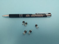
3A Power Input Protection Fuses
Fuses protect the analog inputs from over-current when configured as mAdc inputs. Replacement fuses are available in 5 packs.
50mA Power Input Protection Fuses
Fuses protect the analog inputs from over-current when configured as mAdc inputs. Replacement fuses are available in 5 packs.
Ethernet Cable
CAT 5 cables can be used for connecting the IntelliLogger to a LAN Switch, Hub, Router or expanding a BBus network.
Calibration Certificate
An optional Certificate of Calibration can be provided with the instrument at time of order or up to 6 months after manufacture.
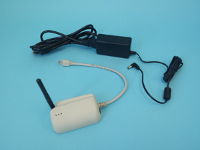
Short-Range WiFi Bridge
With this Bridge, the IntelliLogger can be quickly deployed on a WiFi network. Unit is provided with 120Vac power supply and surface mounting cradle bracket.
