Air Compressor Duty-Cycle Characterization
Characterizing Compressor Run Time with the IL-Mini Data Logger
A key parameter in the assessment of a Compressed Air System is the run-time loading or duty-cycle of a compressor. Understanding the loading characteristics provides insight into the compressor system performance and identification of potential savings, parallel compressor load sharing and/or pending trouble.
Duty-cycle can be simply logged with the IL-Mini™ by connecting an On/Off signal representing the compressor state to the Digital input channel integral to the IL-Mini. This signal could come from a compressor controller output (low voltage), an AC Current Threshold switch, a PLC or other low-voltage signal that is indicative of the On/Off state of the compressor. The IL-Mini™ can then be simply programmed to calculate and log the percentage of time per user defined interval (eg 15 minutes) that the air compressor is ON.
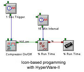
Figure 1 illustrates the icon-based Program Net built within HyperWare-II which will be uploaded into an IL-Mini to data log air compressor run time.
The icon named Compressor On/Off represents the actual hardware digital signal input channel on the IL-Mini. To this input, a digital signal representing the On/Off state of the compressor is connected. In the Program, the state of this compressor signal is checked every second per the connected Sample Rate Clock icon named 1 Sec Trigger. The compressor state is then fed to the Duty-Cycle icon (% Run Time) which calculates the percent of each 15 minute interval that the compressor is ON. Every 15 minutes, this percentage is stored to memory and tagged as % Run Time.
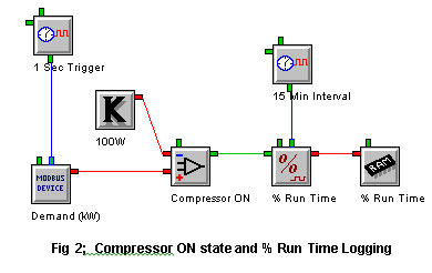
Alternatively, this same Duty-Cycle data can be derived via another method which does not require wiring of a separate digital compressor state signal to the IL-Mini™. Figure 2 illustrates a Program Net that detects when the power level (already being monitored) exceeds a minimum threshold indicating that the compressor is ON.
In the Program Net in Figure 2, the compressor power (demand) is being monitored via a Modbus connected power meter every second. The power level is then compared to a 100W setpoint level with a Comparator icon (named Compressor ON). If the power is greater than 100W it can be assumed that the compressor is ON and the 15 minute interval % Run Time is logged to memory every 15 minutes.