Single Compressor, Basic Supply Side IL-Mini™ Audit Package
With this system, basic parametric data can be collected about the supply side compressor operation including electrical energy, air flow rates, time interval air delivery volume, supply pressure and pressure drop across filters/dryers. Here is how each of the parameters can be measured, characterized and the equipment that is required:
Compressor Electrical Energy
Utilize a 3phase 480Vac WNB Wattnode Power Meter with pulse output and three 50Aac full scale split core CT’s on the compressor 3-phase electrical supply. Via the HyperWare-II program, the pulses can be counted, scaled and totalized every 15 minutes to develop a run profile over the audit period.
Compressor Supply Side Air Flow
Install a CDI-5200 air flow transducer after the filter/dryer on the supply side piping to the plant. The 4-20mA output from this device can then be fed into one of the four analog input channels on the IL-Mini™ and the 4-20mA loop signal scaled accordingly per the meter manufacturer’s instructions within the IL-Mini™ Program Net. Program Net
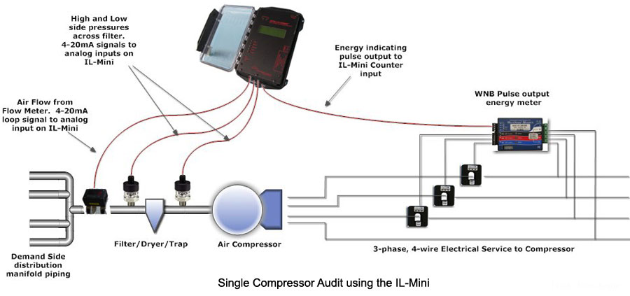
Compressor Supply Side Pressure
Install a 4-20mA loop pressure transducer in the supply side piping on the outlet (downstream or low side) of the filter/dryer. Utilize the Program Net developed with HyperWare-II to scale the 4-20mA loop to PSIG and log the pressure downstream of the filter/dryer side transducer pressure to IL-Mini™ memory. Configure the Program Net to sample the pressure every 10 seconds but only store it to memory if the pressure changes by more than 3 psig since the last value was stored. Implement this powerful data acquisition scheme simply by using the Delta Icon.
Dryer/Filter Pressure Drop
From a flow perspective, Dryer/Filter health can be determined by recording the differential pressure across the Dryer/Filter. In addition to the filter low-side pressure transducer installed for the Supply Side Pressure logging (described above) install a second pressure transducer on the high side (upstream from the filter/dryer). Utilizing the two pressure transducers the Program Net converts their 4-20mA loop signals to pressure then subtracts and stores the differential pressure (dP) to IL-Mini™ memory.. only when the the compressor is running. As this parameter will typically change slowly over time, it may be desired to log the dP only when it changes by some user defined amount… e.g. 0.3psig. Another task simply handled by the Delta icon in the IL-Mini™ Program Net.
For higher accuracy dP measurements, a more sensitive differential pressure transducer may be installed with taps to the high and low side of the filter. The output of this dP transducer (eg 4-20mA) can then be scaled within the IL-Mini, fed through a Delta icon and stored to memory.
Compressor Run-Time Loading
Characterizing compressor run-time provides valuable insight into compressor sizing and the Supply to Demand side match. Logging the percent of time that the compressor is ON can provide this insight. Without the addition of any additional hardwired signals, this parameter can easily be derived and logged by the IL-Mini™ Program Net based on one of the other signals… e.g. the differential pressure across the dryer/filter. The calculated dP (see above) is compared to a threshold of 1psig using a Set-point Icon feeding into one (or more) Duty-Cycle icon in the Program Net. If the set-point pressure is exceeded, the Duty-Cycle icon starts accumulating time. The Duty-Cycle icon can then output the run time per a user defined interval (eg 15 minutes) for storage to memory and later analysis.