ILIM-7 IntelliLogger Analog Input Channel Expansion Module
Isolated 8 channel analog input expansion module for the IntelliLogger™ system.
| ILIM-7 Key Features | |
|---|---|
| Adds 8 High Resolution Isolated analog inputs to IntelliLogger | |
| All channels completely Kelvin isolated simplifying signal and transducer Connectivity | |
| User programmable for uVdc, mVdc, mAdc and thermocouple direct input | |
| Integral cold junction compensation for thermocouple readings | |
| Integral over-current protection | |
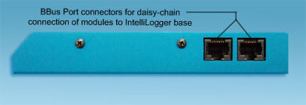
| Simple BBus cable connection for remoting modules away from the ILL base | |
| Automatically recognized by HyperWare-II Software for intuitive setup |
Product Information
Overview
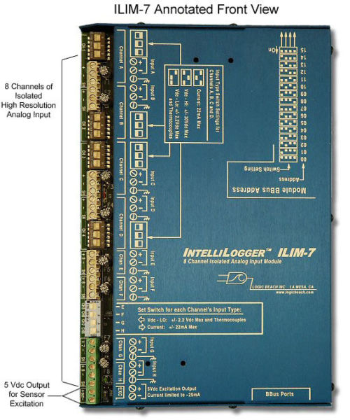
The ILIM-7 is a very high resolution, high accuracy Interface Module containing 8 isolated differential inputs and one excitation voltage output. The desired resolution of the readings can be set by the user from 16 bits (one part in 64,000) to 20 bit (one part in a million). Filtering (e.g. 50 and 60Hz rejection) and extended settling time for higher output impedance signals is supported on a channel by channel basis.
Isolation which is integral to each of the ILIM-7 input channels avoids field installation problems associated with common mode input exceedance issues… making the real-world deployment and configuration of the IntelliLogger faster and easier.
Each input may be individually configured as:
Thermocouple:
Seven types of thermocouple are supported and direct thermocouple connection can be made to any of the ILIM-7 eight channels via the associated terminal strips. J, K, E, T, R, S and N type thermocouples are currently supported.
Cold Junction Compensation for Thermocouple Measurement:
The Cold Junction Compensation (CJC) is handled automatically by the ILIM-7 via an onboard temperature sensor. This sensor can also be accessed for monitoring and/or logging of the actual ILIM-7 unit temperature via the Program Net.
DC Voltage
All 8 isolated inputs can be individually configured for 8 different bipolar DC voltages input ranges. Eight ranges are provided supporting +/-19mV to +/-2.2 Vdc full scale.
Additionally, four of the channels can be configured for full scale input of an additional 3 ranges… +/-7.5Vdc, +/-15Vdc and +/-30Vdc.
DC Current
All 8 isolated channels can be individually configured for DC current measurement as well via the integral precision low TC 100 ohm burden resistor. Eight bipolar DC current ranges are user selectable on a channel by channel basis, ranging from +/-190uAdc to +/-22mAdc full scale.
One stable, 5Vdc output (25mA max current) output is provided on each ILIM-7. This output channel can be used for sensor excitation or other channel reading coincident applications.
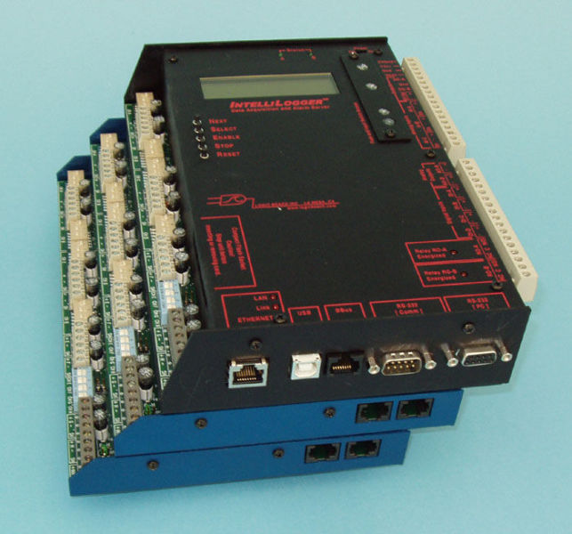
The ILL model IL-80 includes one ILIM-7 Analog Expansion module integral to the package. Additional expansion modules can be connected via the BBus to meet your desired analog and digital I/O needs.
Specifications
| Feature | Channel Qty | Function | Comments |
|---|---|---|---|
| Isolated Analog Input (programmable range) | 8 | Vdc Input ranges: +/-19mVdc +/-39mVdc +/-78mVdc +/-150mVdc +/-300mVdc +/-600mVdc +/-1.2Vdc +/-2.2Vdc +/-7.5Vdc (on 4 chans only) +/-15Vdc (on 4 chans only) +/-30Vdc (on 4 chans only) Thermocouple: J, K, E, T, R, S and N types with both Full and Limited ranges available. mAdc Input ranges: +/-190uAdc +/-390uAdc +/-780uAdc +/-1.5mAdc +/-3.0mAdc +/-6.0mAdc +/-12mAdc +/-22mAdc |
Channels can be field configured independently for bipolar Vdc input, Thermocouple input or mAdc input.
These channels utilize a high resolution ADC providing up to 20 bits of signal resolution (i.e. one PPM). The default is 16 bits (one part in ~64,000) and the setting is user programmable. Channels are all isolated from each other as well as from the system base. When channels are configured for thermocouple applications, the CJC temperature is automatically sensed and used in compensation. Four of the eight channels when configured as Vdc inputs can be programmed to accept 3 additional higher voltage ranges up to 30Vdc. Contact Logic Beach for information about higher Vdc input ranges. |
| 5Vdc Output | 1 | 25mA current limited and regulated 5Vdc output for sensor excitation | Pulsed on under software control. Can be used for sensor excitation. |
The IL-80 model IntelliLogger has one ILIM-7 module integral to the System Base Enclosure and the BBus connection is made internally. Hence, the IL-80 high resolution analog inputs meet the same versatility and specifications as the stand-alone ILIM-7 modules explained here.
Programmability
Using HyperWare-II software, an ILIM-7 Analog Expansion Module connected to an ILL system base is automatically identified. Upon a query of the connected ILL system from within the HWW programming window, icons representing each of the analog input channels are returned to the workspace for configuration and incorporation into the desired data acquisition program.
Accessories
The ILIM-7 is shipped complete and ready for attachment to an ILL System Base.
Optional accessories or parts include:
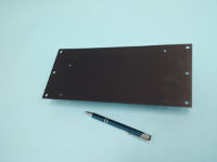
- Surface Mounting Bracket – For attaching ILL or Expansion Modules to a wall or enclosure back.
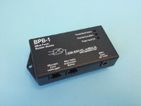
- BPB-1 BBus Power Booster – Injects supply voltage in BBus network for applications with 5 or more Expansion Modules or long BBus cable runs.
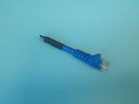
- BBus Termination Stub– The last ILIM-x module in a BBus daisy-chain should have a BBus Termination Resistor stub installed. This stub serves to terminate the RS-485 serial communication link which mimimizes communication errors with the ILL System Base. One Stub is provided at order time.
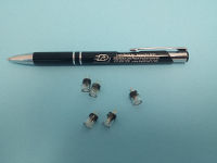
- Replacement Fuses – Fuses protect the analog inputs when configured as mAdc inputs. Fuses are available in replacement 5 packs.
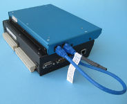
- Module Mounting “Stair Step” Bracket – allows stacking of Expansion Modules and/or attachment to the ILL base.
Documentation
Frequently Asked Questions
- How are ILIM-7 modules added to an IntelliLogger system?
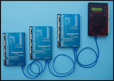
- Expansion modules such as the ILIM-7 and ILIM-2 are simply connected to the IntelliLogger with a standard Cat5 or Cat6 Ethernet cable. The cable routes from the BBus port on the IntelliLogger to one of the two BBus ports on the first expansion module. For an additional module, another cable is connected from the second BBus port on the first module to one of the two BBus ports on the second module. Additional modules are simply daisy-chain connected like this.
- The last module should have a BBus Terminator stub installed into the second unused port to minimize reflected signals.
- Is the ILIM-7 function the same as provided in the eight channels on the left side in an IntelliLogger model IL-80?
- Yes. An ILIM-7 assembly is built into the IL-80.
- How many Expansion modules can I connect to an IntelliLogger System Base?
- Up to 16 modules can be connected although a BPB-1 will be required to inject power after the 4th connected module.
- What does it mean that the ILIM-7 analog input channels are “isolated?”
- “Isolation” on input channels means that they are electrically isolated from other channels and from the ILIM-7 and IntelliLogger instrument main circuitry… This is a very valuable feature that makes wiring of the instrumentation much easier in that the user does not need to worry about currents flowing between channels or to the main instrument… either of which can shift reading values and make life very confusing.
Isolation is extremely valuable when measuring voltages or currents that are not referenced to the same ground potential. This can arise in industrial applications where transmitters or other signals are powered by separate power supplies that are not at a common ground potential. It is not uncommon to see potentials of 10’s of Volts between devices that are “ground referenced” due to the voltage developed on Grounding conductors due to industrial level currents. - Additionally, isolated channels can be used to measure signals in the same circuit that have their negative terminal at different potentials (for example measuring a current across a high side shunt along with another Ground referenced shunt).
- “Isolation” on input channels means that they are electrically isolated from other channels and from the ILIM-7 and IntelliLogger instrument main circuitry… This is a very valuable feature that makes wiring of the instrumentation much easier in that the user does not need to worry about currents flowing between channels or to the main instrument… either of which can shift reading values and make life very confusing.
- How long of Ethernet cable can I run between the IntelliLogger and an Expansion module?
- Each foot of BBus cable and each connection result in wiring resistance and associated voltage drop due to the current running from the IntelliLogger to the module(s). Eventually, this voltage drop will subtract from the voltage supplied to the module such that it will have insufficient voltage to operate. Additional modules will draw more current resulting in more voltage drop on the BBus cable. A calculation can be done for each installation however for quick reference… 100 ft of BBus cabling is commonly used with a single module. If additional modules are required on long runs, the BPB-1 BBus Power Booster can be used to inject additional power into the BBus cabling.
- What function does the “Extend Settling Time” feature serve?
- This user specified time is inserted after an input channel is selected and before the channel is read. It provides additional time for slower sensors that need to settle before readings can be taken. This setting might be changed if a user has a very high output impedance sensor or input divider to which the channel is being connected, or when using Excitation. The fastest setting is the default: zero additional milliseconds. A drop-down list allows the selection of increased settling times, up to almost 2 seconds, with the cost that it slows down the rate at which a channel can be sampled.
- What is the use for the Speed vs Precision slider?
- Setting this slider toward the “Precision” end changes settings in the analog to digital conversion circuitry in the ILIM-7 to take higher resolution readings. However this comes at the expense of speed (sampling throughput) since it takes longer to make a high resolution reading.
Moving the slider toward the “Speed” end reduces the amount of time used to sample an analog input schedule, allowing the channel to be read more quickly although at the loss of absolute resolution.
- Setting this slider toward the “Precision” end changes settings in the analog to digital conversion circuitry in the ILIM-7 to take higher resolution readings. However this comes at the expense of speed (sampling throughput) since it takes longer to make a high resolution reading.
- What is “resolution?”
- The number of divisions into which a full scale range is split.
An ADC (analog to digital converter) takes an analog Full Scale range (eg 10Vdc) and breaks it up into evenly sized parts or bins. When an analog signal (eg a voltage) is converted into a digital value, it then is “sorted” into one of those bins and that value is used for further processing. For example, if an ADC had a full scale input range of 10Vdc and it used an ADC that had a 10 part resolution, then each bin would be 10Vdc/10 = 1Vdc wide. There would be 10 bins… each of them 1Vdc wide.. 0 to 1Vdc, 1 to 2Vdc, 2 to 3Vdc, etc. So if an analog signal of 3.6Vdc was fed into the ADC, it would report that the input signal was in the 4th bin (3 to 4Vdc). - ADC’s resolution is typically referred to in number of bits… for example a 10 bit ADC. A 10 bit ADC would split its full scale input range into 2^10 (2 to the 10th power) or 1024 bins. If the full scale range was 10 Vdc, then each bin would be 10Vdc/1024 or 0.0098V (9.8mV) wide.
- The ILIM-7 uses an extremely high resolution ADC and precision associated circuitry. Depending on the user setting, resolutions of 16 bit which can resolve 1 part in 65,536 up to 20 bit which can resolve 1 part in 1,048,576!
- The number of divisions into which a full scale range is split.
- What types of signals can the ILIM-7 accept?
- To make the ILIM-7 as versatile as possible for the end user, all eight of the input channels can directly read mVdc, Vdc, mAdc and 7 types of thermocouple.. without the need for any user provided external circuitry. Additionally, four of the channels have extra higher voltage ranges and can read a number of ranges up to and including +/-30Vdc.
Ordering
| ILIM-7 | |||
|---|---|---|---|
| Product Name: | IntelliLogger ILIM-7 Isolated Analog Input Expansion Module | ||
| Order Part Number: | 9080.50002 | ||
| Price: | $840 | ||
| | | |||
| Items included with order: | |||
| Product Name: | Part Number: | Qty: | |
| ILIM-7, IntelliLogger Analog Expansion Module | 9080.50002 | 1 | |
| Cable, Cat 5, LAN Cable, Blue, 3′ (when purchased alone) | 9020.50008 | 1 | |
| Cable, Cat 6, LAN Cable, Blue, 1′ (when purchased with an IntelliLogger instrument) | 9020.50005 | 1 | |
| Terminating Stub Connector | 9020.50090 | 1 | |
| | | |||
| Items commonly purchased with this product: | |||
| Product Name: | Order Part Number: | Price: | |
| IntelliLogger Surface Mounting bracket | 3539.30010 | $22 | |
| Module Attachment Bracket; for attachment of additional ILIM-x module(s) to the back of an IntelliLogger. | 3539.30000 | $14 | |
Contact Logic Beach directly to purchase this product.
Contact Logic Beach directly via phone or email with questions and/or to place your order.
Our Applications Staff welcomes your inquiry!
Accessories
BPB-1 BBus Power Booster
Injects supply voltage in BBus network for applications with 5 or more Expansion Modules or long BBus cable runs.
Module Mounting “Stair Step” Bracket
Allows stacking of Expansion Modules and/or attachment to the ILL base.
Surface Mounting Bracket
For surface mounting of an Expansion Modules to a wall or enclosure back.
50mA Input Protection Fuses
Fuses protect the analog inputs from over-current when configured as mAdc inputs. Replacement fuses are available in 5 packs.
Bbus Termination Stub:
The last ILIM-x module in a BBus daisy-chain should have a BBus Termination Resistor stub installed. This stub serves to terminate the RS-485 serial communication link which mimimizes communication errors with the ILL System Base. One Stub is provided at order time.
