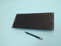
ILIM-2 IntelliLogger Digital Input/Output Channel Expansion Module
Event, Counter, Frequency Input and Digital Output channel expansion module for the IntelliLogger™ system
| ILIM-2 Key Features | |
|---|---|
| Digital Input and Output channel expansion for IntelliLogger | |
| Water and Energy Sub-metering Applications | |
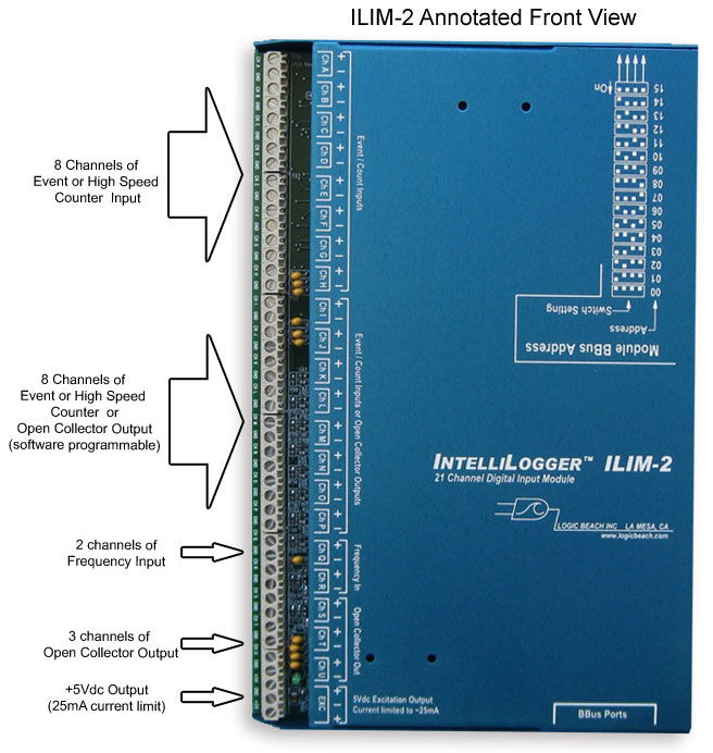
| Adds 8 Event or High Speed Counter Inputs | |
| Adds 8 Event, Counter or Open Collector Outputs | |
| Adds 2 Frequency Inputs | |
| Adds 3 Open Collector Outputs | |
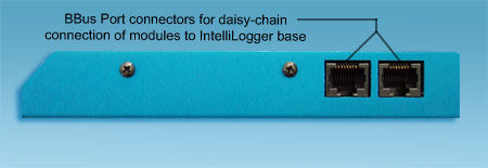
| Simple BBus connection to the IntelliLogger | |
| Can be remoted up to 100ft from IntelliLogger |
Product Information
Overview
The ILIM-2 is a high channel count IntelliLogger family channel expansion module dedicated to Event, Counter and Frequency Input and Open Collector Outputs. As other Expansion Modules, it connects to the IntelliLogger System Base via the daisy-chain BBus… and self-identifies within the HyperWare-II Programming environment for quick and intuitive configuration.
The ILIM-2 Module adds multiple user configurable Input and Output digital channels including:
- 8 channels of Event/Counter Input
- 8 channels of Event/Counter Input or Open Collector Output
- 2 Frequency Inputs
- 3 Open Collector Outputs
- 1 0/+5Vdc Output
The module is well suited to electrical, gas and water Sub-Metering applications, Event logging, Run-Time assessment and power monitoring using pulse output kWh transducers.
Specifications
| Feature | Channel Qty | Function | Comments |
|---|---|---|---|
| Event or Count |
8 (Chans A through H) |
INPUT; Event or High-Speed Count (e.g. for sub-metering apps) Signal Debounce is software configurable on a per channel basis. Fixed integral pull-ups allow for “dry” contact (non-powered switch) inputs. Can also accept Vdc driven input signals up to 12Vdc. Schmitt circuitry adds hysteresis for slower transitioning input waveforms. |
Channels are individually configurable through HyperWare-II as Event or High-Speed Counter inputs.
Event Mode: Input’s state is sampled at a frequency as defined in the IntelliLogger Program Net. Input only stored when it changes state (On to Off or Off to On). Count: Per sample rate in IntelliLogger Program Net, the count total is periodically sampled and stored to memory or used in further processing (e.g. totalization, KWh calculations, volume flow, etc) |
| Event, Count or Open Collector Output |
8 (Chans I through P) |
INPUT or OUTPUT; Event, Count input or Open Collector Output Signal Debounce is software configurable on a per channel basis. Fixed integral pull-ups allow for “dry” contact (non-powered switch) inputs. Can also accept Vdc driven input signals up to 12Vdc. Schmitt circuitry adds hysteresis for slower transitioning input waveforms. Use: Sub-metering inputs and general use outputs |
Same as Inputs above with the addition of Open Collector outputs (100mA max) for each channel with over-current and ESD protection. |
| Frequency |
2 (Chans Q & R) |
INPUT; Frequency input channel. Software controlled pull-ups allow for “dry” contact (non-powered switch) inputs. Can also accept Vdc or AC input waveforms up to +/-12V. |
Connected input signal’s frequency is sampled periodically per the IntelliLogger Program Net and passed along for storage to memory or further processing and calculations.
Input is amplified. Expanded frequency range results when input waveform amplitude is larger. |
| Open Collector output |
3 (Chans S, T and U) |
OUTPUT; Open Collector output |
Output: 100mA. Over-current protected. Frequency Output Mode:Under IntelliLogger Program Net control, these outputs can be configured to generate a varying square wave output as a function of the Program Net parameters. |
| +5Vdc Output | 1 | OUTPUT; +5Vdc regulated output |
Output is under IntelliLogger Program Net On/Off control. Current limited to approximately 25mA |
The IL-90 model IntelliLogger has one ILIM-2 module integral to the System Base Enclosure and the BBus connection is made internally. Hence, the IL-90 digital inputs meet the same versatility and specifications as the stand-alone ILIM-2 module explained here.
Programming
Using HyperWare-II™ software, an ILIM-2 Digital Expansion Module connected to an IntelliLogger™ system base is automatically identified. Upon a query of the connected IntelliLogger™ system from within the HyperWare™ programming window, icons representing each of the digital input and output channels are returned to the workspace for configuration and incorporation into the desired data acquisition program.
Accessories
The ILIM-7 is shipped complete and ready for attachment to an ILL System Base.
Optional accessories or parts include:
- Surface Mounting Bracket – For attaching ILL or Expansion Modules to a wall or enclosure back.
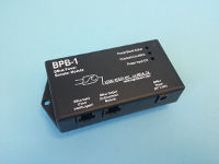
- BPB-1 BBus Power Booster – Injects supply voltage in BBus network for applications with 5 or more Expansion Modules or long BBus cable runs.
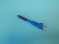
- BBus Termination Stub– The last ILIM-x module in a BBus daisy-chain should have a BBus Termination Resistor stub installed. This stub serves to terminate the RS-485 serial communication link which mimimizes communication errors with the ILL System Base. One Stub is provided at order time.
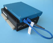
- Module Mounting “Stair Step” Bracket – allows stacking of Expansion Modules and/or attachment to the ILL base.
Documentation
Frequently Asked Questions
- How are ILIM-2 modules added to an IntelliLogger system?
- Expansion modules such as the ILIM-7 and ILIM-2 are simply connected to the IntelliLogger with a standard Cat5 or Cat6 Ethernet cable. The cable routes from the BBus port on the IntelliLogger to one of the two BBus ports on the first expansion module. For an additional module, another cable is connected from the second BBus port on the first module to one of the two BBus ports on the second module. Additional modules are simply daisy-chain connected like this.
- The last module should have a BBus Terminator stub installed into the second unused port to minimize reflected signals.
- Is the ILIM-2 function the same as provided in the eight channels on the left side in an IntelliLogger model IL-90?
- Yes. An ILIM-2 assembly is built into the IL-90.
- How many Expansion modules can I connect to an IntelliLogger System Base?
- Up to 16 modules can be connected although a BPB-1 will be required to inject power after the 4th connected module.
- How long of Ethernet cable can I run between the IntelliLogger and an Expansion module?
- Each foot of BBus cable and each connection result in wiring resistance and associated voltage drop due to the current running from the IntelliLgger to the module(s). Eventually, this voltage drop will subtract from the voltage supplied to the module such that it will have insufficient voltage to operate. Additional modules will draw more current resulting in more voltage drop on the BBus cable. A calculation can be done for each installation however for quick reference… 100 ft of BBus cabling is commonly used with a single module. If additional modules are required on long runs, the BPB-1 BBus Power Booster can be used to inject additional power into the BBus cablilng.
- What types of signals can the ILIM-2 accept?
- The ILIM-2 was designed to accept “digital signals”.
- Event inputs – whenever an input changes state from High to Low or Low to High the transition direction and time is stored to memory. Event inputs come from switch states, door open/close, alarm outputs, etc.
- Counter inputs – pulse counting or totalizing. For example from positive displacement flow meters where each pulse corresponds to a unit of volume. The pulses come into the ILIM-2 channel and are counted asynchronously in a hardware counter inside the module. This totalized count is then read from the ILIM-2 counter based on the sampling frequency user defined in the IntelliLogger Program Net. Follow-on Math icons then typically convert this count to Engineering units such as gallons, Watt-hours, etc.
- Frequency inputs – many flow devices such as water meters or wind speed anemometers output a frequency that is a function of the flow rate. The Frequency inputs sample this frequency and log it to memory based on the Program Net. Follow-on Math functions in the Program Net then typically convert the frequency to Engineering units such as GPM, mph, etc.
- The ILIM-2 was designed to accept “digital signals”.
- If the open-collector outputs of the ILIM-2 are used to drive relays, should any precautions be taken?
- Yes, never connect any of the Intellilogger system components to voltages above Class II (ie 30V).
- Additionally, if inductive loads are driven (such as relay coils), a bipolar transzorb should be installed across the coil to quench the inductive voltage induced when the inductive load (eg relay coil) is de-energized. When the inductor is de-energized, the magnetic flux around the coil collapses and attempts to keep the current flowing.. even though the circuit is open. This impresses very high voltages across the open terminals (ie the open collector switches in the ILIM-2) which can be damaged. The clamping transzorb across the inductor terminals will serve to short this current, dissipating the voltage potential.
Ordering
| ILIM-2 | |||
|---|---|---|---|
| Product Name: | IntelliLogger ILIM-2 Digital Input/Output Expansion Module | ||
| Order Part Number: | 9080.50001 | ||
| Price: | $780 | ||
| | | |||
| Items included with order: | |||
| Product Name: | Part Number: | Qty: | |
| ILIM-2, IntelliLogger Digital channel Expansion Module | 9080.50001 | 1 | |
| Cable, Cat 5, LAN Cable, Blue, 3′ (when purchased alone) | 9020.50008 | 1 | |
| Cable, Cat 6, LAN Cable, Blue, 1′ (when purchased with an IntelliLogger instrument) | 9020.50005 | 1 | |
| Terminating Stub Connector | 9020.50090 | 1 | |
| | | |||
| Items commonly purchased with this product: | |||
| Product Name: | Order Part Number: | Price: | |
| IntelliLogger Surface Mounting bracket | 3539.30010 | $22 | |
| Module Attachment Bracket; for attachment of additional ILIM-x module(s) to the back of an IntelliLogger. | 3539.30000 | $14 | |
Contact Logic Beach directly to purchase this product.
Contact Logic Beach directly via phone or email with questions and/or to place your order.
Our Applications Staff welcomes your inquiry!
Accessories
BPB-1 BBus Power Booster
Injects supply voltage in BBus network for applications with 5 or more Expansion Modules or long BBus cable runs.
Module Mounting “Stair Step” Bracket
Allows stacking of Expansion Modules and/or attachment to the IntelliLogger base.
Surface Mounting Bracket
For surface mounting of an Expansion Modules to a wall or enclosure back.
Bbus Termination Stub:
The last ILIM-x module in a BBus daisy-chain should have a BBus Termination Resistor stub installed. This stub serves to terminate the RS-485 serial communication link which mimimizes communication errors with the ILL System Base. One Stub is provided at order time.
